Service
H&P Advanced Technology provides professional project services. This begins with the preparation of the product requirement specification in the design phase followed by comprehensive e.g. 3D-Simulation, creating functional specification of the system, layout, construction, prototyping, design verification tests, product release with all necessary documentation such as user manual and service documentation.
We offer services in the following areas:
- High frequency development
- Hardware Design
- FPGA/Microcontroller
- High frequency measuring technology
- Vacuum technology for different applications (NDT, Explosive detection system (EDS), Medical Technology etc.)
- Simulation (CST, ADS, Thermal, Thermomechanical etc.)
Examples from different projects
1.Linearization of a nonlinear power amplifier
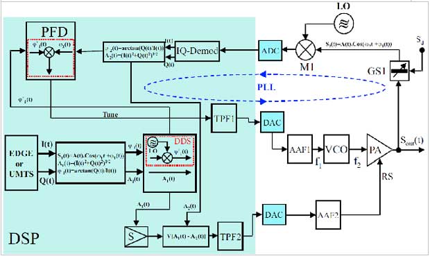
Figure: Schematic of a Polar-Loop method
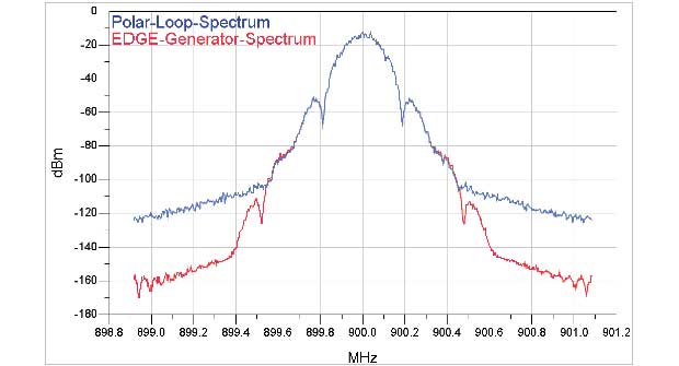
Figure: FFT-Power spectrum of a modulated EDGE-Signal after adjusting the bandwidth
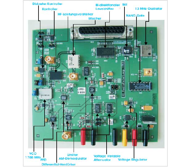
Figure: Realization of the Polar-Loop Tx-circuit for 1700 MHz

Figure: Measurement of the output signal
a.) Signal generator SMIQ 06B
b.) Spectrum of the GSM-EDGE-Signal after the
Polar-Loop Tx-circuit (Bandwidth of the control loops has been adjusted)
2.Millimeter wave imaging system
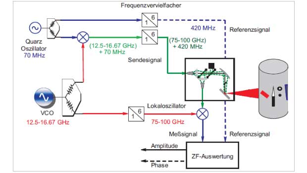
Figure: Simplified block diagram of the system concept

Figure: 19-inch baseband module (top view)

Figure: 19-inch baseband module: Bottom view with integrated IF-signal processing
3.Multi channel control unit for PIN-Diode switches
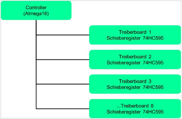

Figure: System concept for a multi channel control unit

Figure: Channel Board
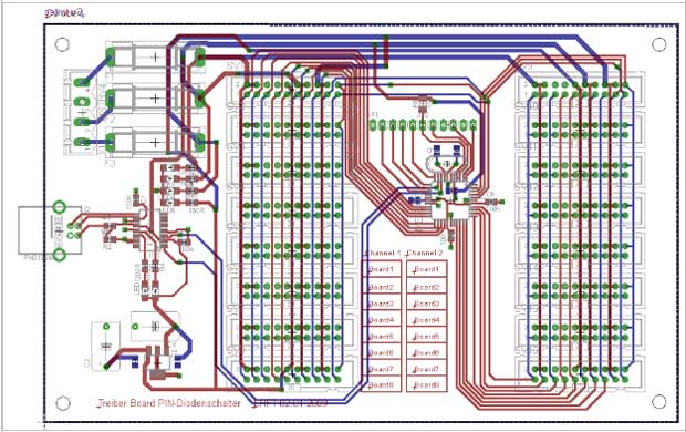
Figure: Driver Board

Figure: PIN-Diode switch Board
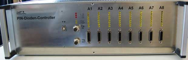
Figure: PIN-Diode-Controller with 64 channels
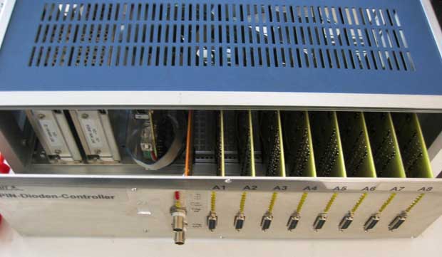
Figure: Front view of the PIN-Diode-Controller
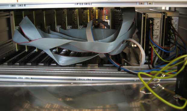
Figure: Back view of the PIN-Diode-Controller
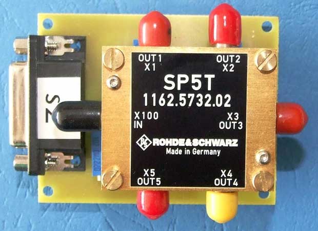
Figure: 1 to 5 PIN-Diode switch
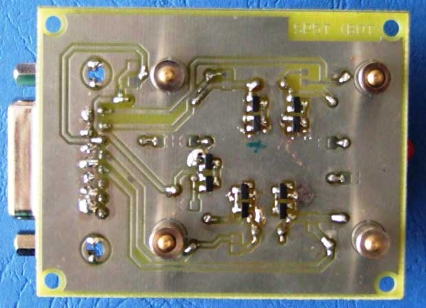
Figure: Back view of the PIN-Diode switch Board
4.Antenna design: Splinehorn 75-100 GHz
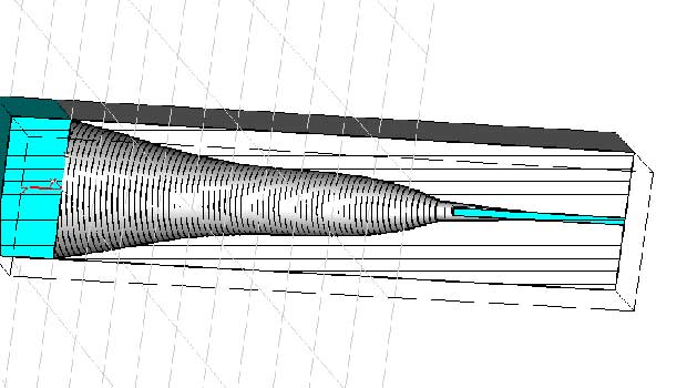
Figure: CST Microwave Studio Simulation of a Splinehorn at 75-100 GHz

Figure: Simulation result of the gain of the Splinehorn at 87.5 GHz
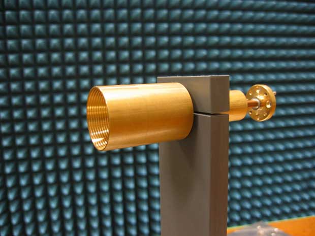
Figure: Realization of the Splinehorn at 75-100 GHz

Figure: Measured reflection coefficient of the Splinehorn at 75-100 GHz
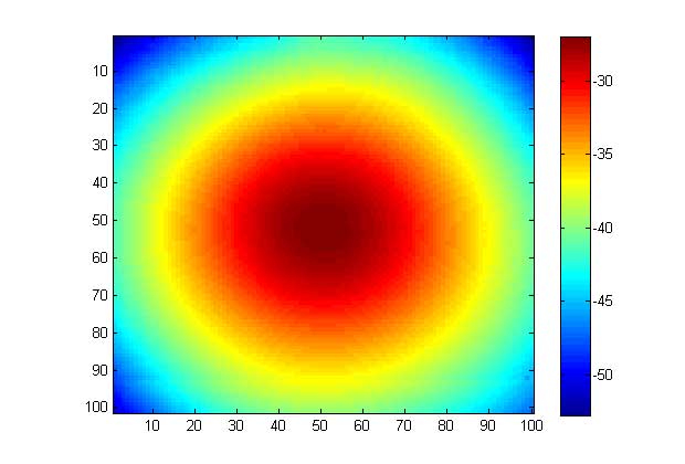
Figure: Measured Spot of the Splinehorn averaged over all frequency points 75-100 GHz
5.Filter design: Ceramic-Bandpass-Filter 12-18 GHz
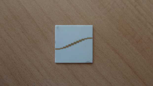
Figure: Coupled-Line Ceramic-Bandpass-Filter 12-18 GHz

Figure: Measured reflection coefficient S11

Figure: Measured transmission coefficient S21