Radar Technology
Use of radar technology in a millimeter wave imaging system
In recent years an increasing interest in the commercial application of millimeter wave systems has been observed. In the past this frequency range was reserved for the classic application fields like radio astronomy and military use. Due to the rapid developments in the semiconductor sector, the cost of millimeter wave components moved to an affordable level that allows commercial use. Thus, the development of imaging systems and sensor measurement techniques has been favored in this frequency range.
A large potential opens up for non-destructive imaging testing of materials. Inhomogeneities in ceramics and plastics can be discovered. In automotive engineering, for example, radar sensors for adaptive cruise control (ACC: Adaptive Cruise Control) are used to determine the distance and the speed of a vehicle ahead. Currently the potential of millimeter wave imaging systems for access control of security-related facilities are examined. These systems are able to detect metallic and non-metallic objects carried by humans.
Active systems are characterized by the fact that non-conductive or weakly conductive measurement objects are penetrated by the electromagnetic wave and reflection and diffraction phenomena occurs at inhomogeneities. In order to create a large image of measurement objects located in the measurement area under real time conditions, the ideal solution is a fully electronic, coherent system. The entire imaging area would be covered with a two-dimensional array of transmitting and receiving elements. The elements must be controllable by a complex switching network and the received signals are processed in parallel. This allows a phase evaluation of the detected signal and provides additional information of the target. However such a concept cannot currently be realized in the millimeter wave frequency band due to cost reasons. A compromise solution represents a linear array which is mechanically moved over the target. As the number of transmitting and receiving elements depends on the spatial sampling criterion, scanning in a lower frequency range would result in a smaller number of components. Another advantage is the cost-effective availability of critical system components. The disadvantage of the lower frequency range, however, is the associated lower range and spatial resolution.
Active millimeter wave imaging systems
Conventional radar systems are used for locating and determining the speed of moving targets. The applications of radar systems ranging from air traffic control, soil and material investigations to radar sensors in the automotive sector. Active imaging systems are also based on the radar principle. The advantage of active systems is that the relationship between the transmitted signal and received signal is known. Thus distance information can be determined on the basis of the reflected receive signal. From the two-dimensional intensity distribution and the distance information, a three-dimensional radar image can be created. In Figure 1 the active millimeter wave imaging principle is shown. To achieve a high spatial resolution, either a focused or unfocused method can be used. The focusing offers the advantage that the representation of the measurement data can take place in real-time. However, due to the aligned reflection the measurement result will be influenced by the geometry of the objects. In case of focusing with an optical element, the spatial resolution is diffraction limited (Rayleigh resolution criterion). The strong angular dependence can be reduced with an unfocused method. This results in a strong decrease of received power and complex signal processing. In contrast to passive imaging an active illumination source is used to receive information about the target from the backscatter signals. The power of a generator will be focused and emitted into the observation area via an antenna. Depending on the application a pulsed signal, a continuous wave signal or a continuously a discretely modulated transmit signal is used (Frequency Modulated Continuous Wave, FMCW or Stepped Frequency Continuous Wave, SFCW). The reflected signals from targets will be detected and evaluated by a coherent radar receiver. The reflection depends on the geometry and material characteristics of the target. The coherent recording of the reflected signals is a crucial advantage of the active imaging principle because it represents the basis for all signal processing algorithms. This creates the possibility of a numerical image reconstruction. To evaluate the imaging system the lateral resolution is used, that means the non-ambiguous detection of two adjacent targets.
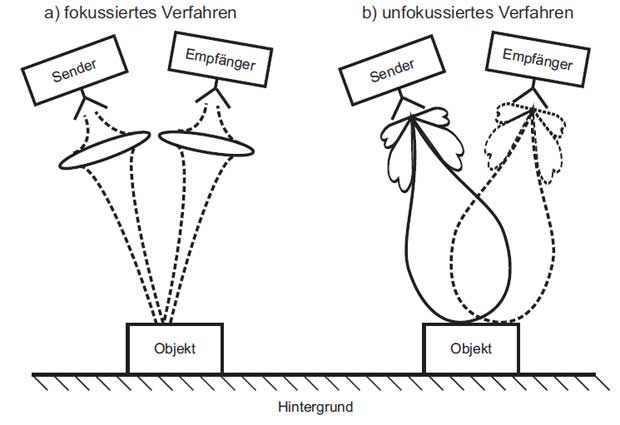
Figure 1: Principle of active imaging systems
In the literature different scanning strategies and measurement setups are indicated for imaging. The image pixels can be scanned in the simplest way sequentially with one channel. To shorten the measurement time, a parallel image acquisition of the entire scene with a multi-channel system is aimed. However compromises for a practical realization must be accepted. This mainly concerns the selection of the frequency range and the limited available components due to financial reasons. Ideally you will use a large-scale two-dimensional receive array of detectors for real-time applications. Because of cost reasons, a linear array of detectors is mechanically moved around the target. This unfocused measurement setup is dependent on a subsequent image reconstruction.
Another possibility is the use of lenses to focus the reflected radiation onto the detector array. This corresponds to the image pixels of a CCD-chip (Charge Coupled Device) used in optical imaging systems. In the millimeter wave range MMIC-chips are used in focal plane cameras. The MMIC-chips are arranged in a large sensor array. Thus on the one hand a compact structure can be realized and on the other hand to take an almost real-time image by simultaneous recording.
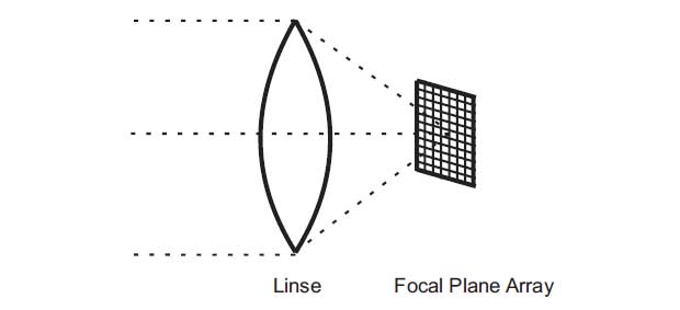
Figure 2: Principle of a focal plane camera
Figure 2 shows the principle of a focal plane camera. This so-called Focal Plane Array principle (FPA) is based on the fact that the incident electromagnetic radiation from the object plane is transformed with the help of a focusing element into the focal plane. Depending on the direction of arrival of the incoming signal, different foci will be generated. If using a parallel image acquisition these foci are filled with receiver elements. Each receiving element of the array is responsible for an image section and thus represents a pixel of the image. The achievable packing density of the antenna elements plays a decisive role because it affects the image quality and measurement time. The disadvantage of this so-called Focal Plane Array principle (FPA) for a compact design is the limited coverage, which is limited by the small aperture size of the lens. In addition the required packing density within the focal plane arrays cannot be achieved in order to record all spatial frequencies simultaneously. The problem can be solved by a so-called micro-scanning. Here, a movable flat mirror is used to capture the array elements located between the pixels.
Resolution of imaging radar systems
The radar method operates according to the echo principle and uses reflected electromagnetic waves in order to obtain information about the target. A transmitter in combination with an antenna is used to focus and emit the electromagnetic wave into the target area. The result is that the electromagnetic wave will be partly absorbed and partly reflected at different targets. This reflected component is evaluated in the receiver for the detection and determination of the target. The evaluation can be done by the amplitude, frequency, phase, polarization or time delay. Hence the information about the position, speed, structure, size and material of the object can be determined. That means a classical radar system is a tracking system for recording and locating an object. However, nowadays aircraft- and satellite-based radar systems offer the possibility of a two-dimensional image of the overflown area. The reflection depends on the geometrical, structural, and material composition of the target object or surface. Differences in the condition of the earth's surface can be determined. You can distinguish water from land, buildings and roads from farmland. In addition it is even possible to recognize different agricultural land. Also information from areas immediately below the surface can be gained. The penetration depth of the electromagnetic wave depends on the used wavelength and on the electrical characteristics of the surface. The main criteria for judging the quality of a radar system are the achievable range, the resolution and accuracy. However it can be assumed that the image quality of a radar system cannot be compared with an optical system. The crucial advantage of a radar system is the fact that it delivers images of the area independently of time of day and weather conditions.
Resolution limits of real aperture radar
An important parameter in the interpretation of radar images is the geometrical resolution. The geometrical resolution indicates the minimum distance of two adjacent targets under which the two objects can be separately identified. A distinction must be made between spatial resolution and range resolution.
The lateral resolution of a real aperture radar transverse to the range direction is determined by the antenna characteristics. In contrast, the range resolution essentially depends on the pulse duration or the bandwidth of the transmitted signal.
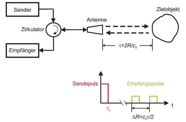
Figure 3: Operation principle of a pulse radar
To illustrate the range resolution the principle of pulse radar in Figure 3 is used. Via an antenna a pulsed signal with a pulse duration τp is emitted. If the signal impacts two spatially separated objects, a superposition of the reflected pluses could occur depending on the time delay. Objects which have a time overlap to a certain degree can be still spatially separated. Based on the received signal, the dividing line between the end of the first object and the beginning of the second object can be determined. The following value can be given as the limit of the range resolution of a radar system:

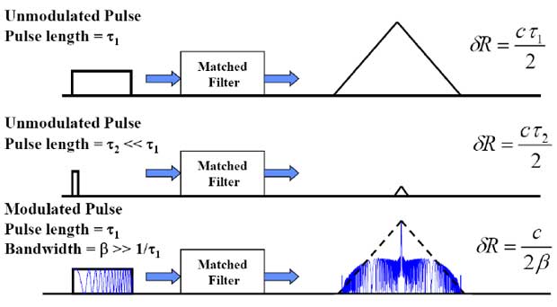
The resolution in range direction δr depends on the bandwidth B of the transmitted signal. An improved range resolution can be achieved by increasing the bandwidth or by reducing the pulse duration. However it must be taken into account that reducing the pulse duration leads to a lower average transmitting power. It is not possible to provide an arbitrarily high average transmitting power within a short period of time. Since the maximum achievable range and signal-to-noise ratio according to the radar equation is affected by the average transmitting power, reducing the transmitting power is simultaneously connected with a reduced range and system dynamics. The problem is that the parameters pulse duration and transmitting power have opposite impacts. Therefore, instead of reducing the pulse duration a linear frequency modulation of the transmitted pulses is used. This is a pulse compression which has a higher time-bandwidth product. The result after the impulse compression is that the frequency-modulated signal (chirp) has a comparable bandwidth and thus has the same range resolution as a short duration pulse. The effect of the impulse compression illustrates Figure 4.
The lateral resolution of real aperture radar is defined with the 3-dB width of the antenna main lobe. The angular resolution in azimuth Θa of a real horn antenna with an aperture diameter D and homogeneous aperture coverage can be noted as follows:

The lateral resolution δa of real aperture radar with distance of R0 is:

An improvement in lateral resolution can be achieved by a shorter wavelength or a larger antenna aperture. However, because of the available installation space it is not possible to increase the antenna aperture arbitrarily. Another possibility is the use of synthetic aperture radar.
Basic principle of synthetic aperture
Synthetic aperture radar systems are used in the field of remote sensing. The numerous applications in imaging the earth's surface include, for example oceanography, cartography, agriculture and forestry and the detection of marine pollution in the area of environmental protection.
To explain the basic principle of the synthetic aperture a typical scenario is taken from remote sensing. The two-dimensional scanning of an area is shown in Figure 5. Here, the terms distance and azimuth direction will be introduced. The azimuth dimension corresponds to the direction of flight. The range direction is determined by the orientation of the transmitting and receiving antenna. The width of the image strip is called as swath.
The basic idea of the synthetic aperture is that the magnitude and phase parameter of receiving signals from a point target can be recorded as long as it is within the real antenna aperture during the flyby. Each target point within the illuminated area has due to the different distance and spatial orientation of the antenna a characteristic receiving signal. Based on the continuous radar signature it is possible to resolve neighbouring point targets.
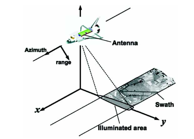
Figure 5: Image geometry of a side-looking radar in swath mode
Resolution of synthetic aperture radar
The range resolution of radar depends on the pulse duration or the bandwidth of the transmitted signal. Thus the range resolution of a SAR system is not different to real aperture radar.
In contrast to the real aperture, synthetic aperture radar achieves a much higher resolution in the azimuth direction by exploiting the coherence of the continuously recorded radar signals.
The formation of the synthetic aperture is illustrated by Figure 6. During the flyby, the radar system constantly records the coherent signals reflected from the target area. A point target within the area is first detected at the radar system position 1. The observation period in which information about the target point A can be recorded, extends to the third position. The principle of synthetic aperture is equivalent to a line consisting of the real antenna elements which are arranged along the flight path. The number of antenna elements depends on the number of recording positions. Compared to the real aperture, the synthetic aperture gets a better angular resolution.
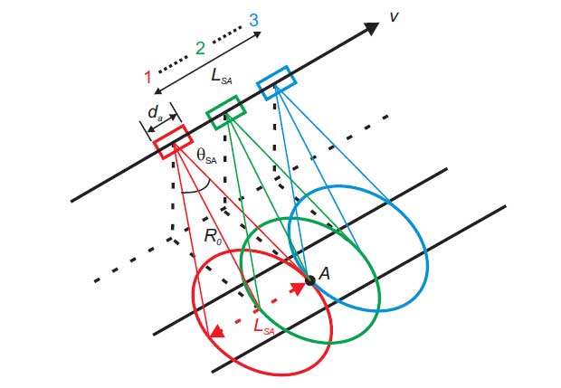
Figure 6: Principle of the lateral resolution of a synthetic aperture radar

The improvement in angular resolution by a factor of 2 results from the fact that the phase gradient or the path object-antenna in the case of synthetic aperture radar is twice as large. This fact can be explained that real aperture radar transmits simultaneously with all antenna elements and the phase difference can only occur on the way back from the object to the antenna. In contrast the antenna elements of radar with synthetic aperture transmit separately and at different times. Therefore the phase difference of both the transmit path (radar-target) as well as the return path (target-radar) must be taken into account.
The maximum length of the synthetic aperture can be determined as follows:

The maximum angular resolution of the synthetic aperture is:

Thus the lateral resolution δSA of synthetic aperture radar is the product of angular resolution and distance.

The lateral resolution is independent of the wavelength λ and the distance R0. Objects whose dimensions are equal to half the antenna length can be resolved separately. Thus, in contrast to real aperture radar, an increase in resolution corresponds with a smaller antenna area or a large antenna beamwidth. A large antenna beamwidth leads to a larger synthetic aperture length LSA.
Selected measurement objects
For the evaluation of the image quality appropriate measurement objects are needed. Different dielectrics with different thicknesses were selected. The dimensions of each object can be seen in Figure 7.
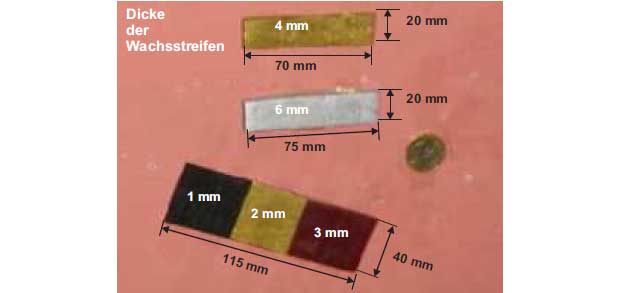
Figure 7: Measurement object consisting of layered wax strips and a 1 Euro coin
The measurement objects were mounted on a planar surface consisting of silicone rubber. In addition, measurement objects were placed as reference points within the scanning area. Such a metallic reference point is the 1 Euro coin.
Focused measurement setup
Figure 8 shows the principle of the focused measurement setup. The complete measurement setup consists of a network analyzer, transmitting and receiving antenna and a target holder. The network analyzer is used to generate the transmission signal and for processing of the received signal. The transmitting and receiving antenna are connected to the network analyzer by flexible dielectric waveguides. This offers the advantage that not the entire measurement system must be moved during the imaging process. Because the working distance from the measurement system to the measurement object is 45 cm, additional focusing elements like polyethylene dielectric lenses are required. The lens focuses the radiated antenna signal to the target, which is reflected depending on the measurement object and is evaluated by the network analyzer.

Figure 8: Principle of a focused imaging system
With this setup ​​the result shown in Figure 9 could be obtained. The measurement objects are clearly visible. However both the diagonally arranged wax strip and the coin show strong diffraction effects at the edges.
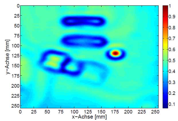
Figure 9: Results of the amplitude summation over 51 frequency points in the frequency range of 90-100 GHz of the measurement object scanned with the focused measurement setup
Unfocused measurement setup
The sketch and the mechanical realization of the unfocused measurement setup are shown in Figure 10 and 11.
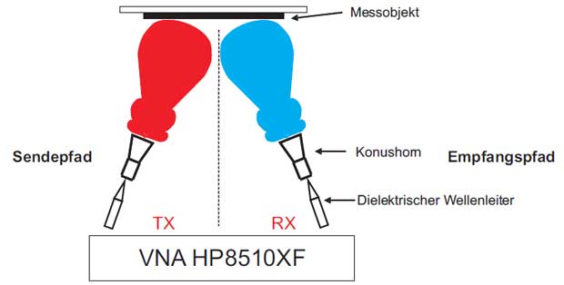
Figure 10: Principle of an unfocused imaging system
The unfocused setup is similar to the previously described setup except the polyethylene dielectric lenses. However the smaller effort for designing focusing elements must be compensated by a more complex SAR signal processing. Because the lateral dissolution of a SAR processing is determined by the length of the synthetic aperture, a large illumination of the target should take place contrary to a focused system. The aperture diameter of the 20 dB horn is 13.7 mm. Thus theoretically a lateral resolution of 6.85 mm can be achieved.
Due to the smaller space requirement, a quasi-monostatic operation can be realized. The distance between the conical horn antennas was selected in such a way that only extremely small crosstalk between the antennas arise.
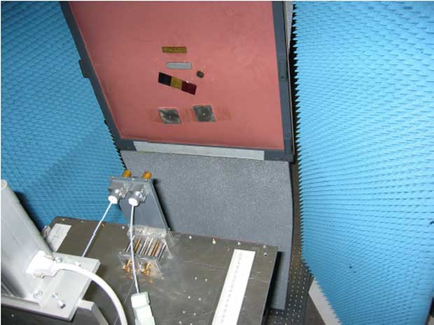
Figure 11: Unfocused quasi monostatic imaging system with conical horn antennas
In Figure 12 and 13 the results of the 2D-SAR reconstruction is shown. The comparison with Figure 9 shows that a significant improvement in lateral resolution can be reached with the unfocused measurement. The shape and edges of the test objects are more highlighted.
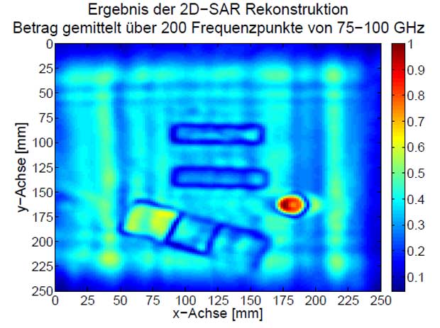
Figure 12: Results of the amplitude summation over 200 frequency points in the frequency range of 75-100 GHz after the SAR-processing of the pixel-by-pixel scanning of the measurement object
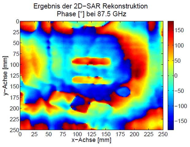
Figure 13: Phase at 87.5 GHz after the SAR-processing of the pixel-by-pixel scanning of the measurement object

Figure 14: Measurement setup for data recording in a cylindrical coordinate system
The results in Figure 15 and 16 confirm the error-free cylindrical 2D-SAR processing. The shape of the metal scissors, the ceramic knife, the euro coins and the wax strip can be clearly identified after the SAR processing in both the amplitude and the phase image. Based on the reconstructed SAR data further image processing algorithms for feature extraction could be used.

Figure 15: Results of the amplitude summation over 200 frequency points in the frequency range of 75-100 GHz after the SAR-processing of the pixel-by-pixel scanning of the measurement object
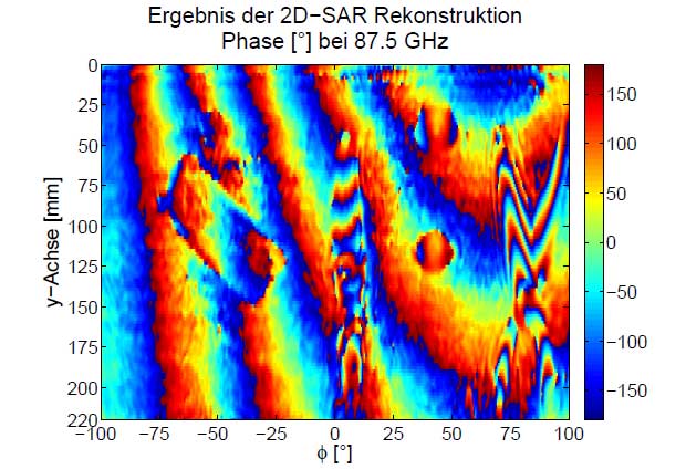
Figure 16: Phase at 87.5 GHz after the SAR-processing of the pixel-by-pixel scanning of the measurement object
Implementation of the system concept
Once the potential of real-time imaging approach has been demonstrated, a suitable system concept had to be realized. Additionally a concept was developed for the synchronization of data acquisition. The operating mode of the system concept is described only on the basis of a simplified block diagram. Because of previous insights a broadband concept for a subsequent adjustment of the focal plane must be designed. The broadband measurement system must provide at each frequency point magnitude and phase information for the subsequent SAR signal processing. Therefore a discrete frequency-modulated process would be a good solution (SFCW process (Stepped Frequency Continuous Wave)).
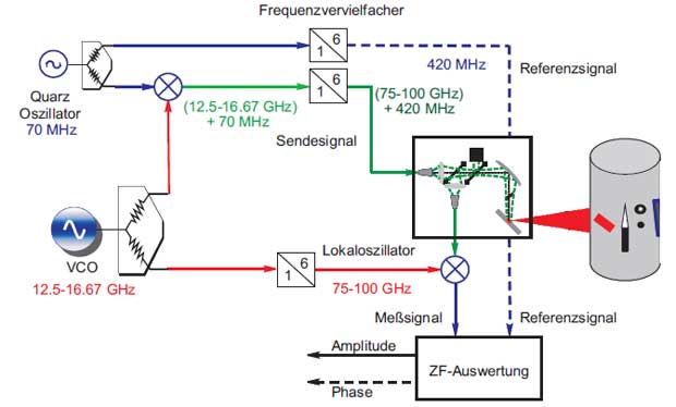
Figure 17: Simplified block diagram of the system concept
From the preliminary studies the following specifications for the measuring system and the required data rate can be derived:
- coherent SFCW-system in the frequency range of 75 to 100 GHz
- Multi-channel operation ability of the transceiver unit for simultaneous evaluation of multiple antenna modules without switching between channels
- Arbitrary number of measured frequency points
- Computer interface for data acquisition must have a data rate of 1 MS/s to record the amount of data within the measurement time
- Synchronization of the different transmit/receive antennas is required
First, the system concept was examined using the simulation program Advanced Design System (ADS) and with ideal components. Then electronic components were selected based on the specifications of the manufacturers. The system concept in Figure 17 is divided into different sections. A distinction is made between the baseband section, the transmitting and receiving unit. The baseband section includes all the components that are responsible for signal generation and signal analysis. In the transmitting and receiving unit, all components are combined that are used for frequency conversion into the range 75 - 100 GHz and into the fixed intermediate frequency.
The principle of SFCW system is based on a broadband tunable VCO source (12.5 - 16.67 GHz). The target frequency range of 75 to 100 GHz is achieved by using a discrete frequency multiplier. The transmitted signal contains an additional frequency shift of 70 MHz, which is derived from the VCO source and a highly stable crystal oscillator. This has the advantage that the signal processing can be performed at a fixed intermediate frequency of 420 MHz. The reference signal is obtained by using the quartz oscillator and a frequency multiplier. The evaluation of the received signal is performed with commercially available Analog Devices AD8302 amplitude-/phase detectors.
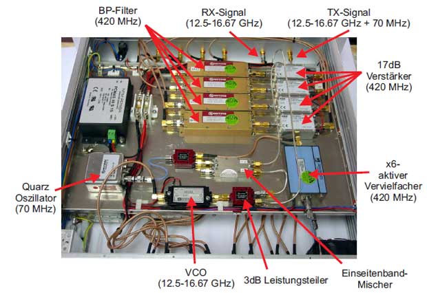
Figure 18: 19-inch baseband module (top view)
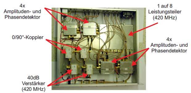
Figure 19: 19-inch baseband module: Bottom view with integrated IF-signal processing
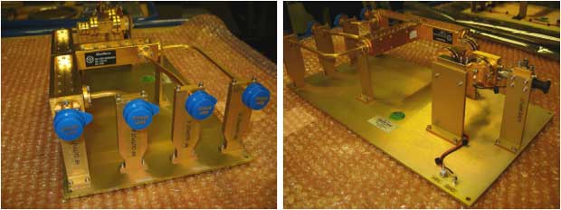
Figure 20: 4-channel transmitter unit, consisting of a frequency conversion chain and a subsequent 3dB-coupler network
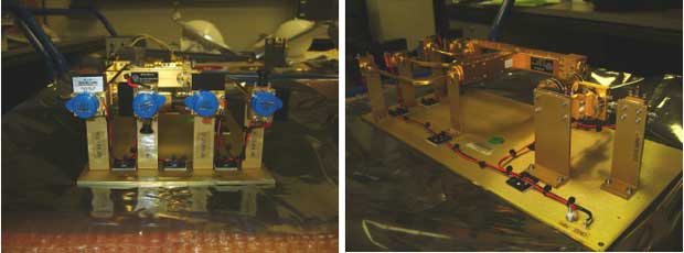
Figure 21: 4-channel receiver unit, consisting of four frequency mixers, a frequency conversion chain and a subsequent 3dB-coupler network